


・Features of the MechaTransRD-Series
・The operating principle of the MechaTransRD-Series
・Applications of the MechaTransRD-Series
・List of the MechaTransRD-Series
・Operating precautions for MechaTransR
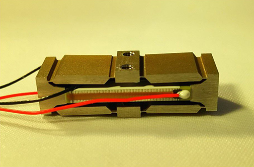
The MechaTrans®D-Series is a compact piezoelectric actuators that can generate large output strokes, which is 10 times and above larger than the stroke of a multilayer stacked piezoelectric actuator. The MechaTrans®D-Series consists of a stroke magnification / amplification structure and multilayer stacked piezoelectric actuators. With the stroke magnification structure, the stroke is magnified to overcome the limitation of the multilayer stacked piezoelectric actuator. The MechaTrans®D-Series is designed flat and compact in size, therefore the efficiency of the space utilization is high. The output stroke is converted to 90 degree in direction compare to the original output stroke of the multilayer stacked piezoelectric actuator. When a voltage is applied to the MechaTrans®D-Series, it shrinks as shown in Fig. 2.
Features of the MechaTransRD-Series
・large output stroke
・Flat and compact.
・Output stroke of the piezoelectric actuators is converted to 90 degrees in direction.
・The MechaTransRD-Series shrinks as Fig. 2 when a voltage applied.
・Output stroke direction is opposite to the MechaTransRDD-Series
The operating principle of the MechaTransRD-Series
Mechanical tapped holes are fabricated at both sides of the MechaTransRD-Series. Lead wires of red and black(white) are attached at the piezoelectric actuators. Fig. 1 shows an example of the connection between the driver and the piezoelectric actuators. A resistance may be needed in between depend on the driving conditions. When a voltage is applied to the piezoelectric actuators, the MechaTransRD-Series shrink as shown in Fig. 2.
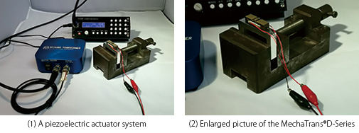
Fig.1 The piezoelectric actuator system
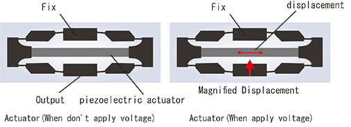
Fig.2 Operating principles of the MechaTransRD-Series
Applications of the MechaTransRD-Series
These are some examples of the application of the MechaTransRD-Series.
・Positioning stage for lithography process
・Auto focus module for a camera.
・Precision pump
List of the MechaTransRD-Series
<MTD Series>
| Outline dimension [mm] WxDxH |
Displacement [μm] *1 |
Blocked force [N] *1 |
Stiffness [N/μm] *1 |
Resonance frequency [Hz] *1 *2 |
Capacitance [μF] *1 |
Solid Model |
Price [¥] |
|
| MTD03S50F3 Datasheet Download |
15×3×5 | 50 | 3 | 0.06 | 2000 | 0.03 | 100,000 | |
| MTD08S250F27 Datasheet Download |
22×8×8 | 250 | 27 | 0.11 | 790 | 0.85 | 85,000 | |
| MTD08S300F25 Datasheet Download |
26×8×8 | 300 | 25 | 0.08 | 500 | 0.85 | 90,000 | |
| MTD16S750F90 Datasheet Download |
50×16×14 | 750 | 90 | 0.12 | 290 | 8.5 | 120,000 |
*1 : Nominal value
*2 : Blocked-Free
Operating precautions for MechaTransR
Please confirm the following operating precautions before using MechaTransRD-Series.
2)Continuous DC voltage under high humidity
3)Avoid excess tensile force against PZT and/or compression force to the arm
4)Do not superimpose DC voltage instantaneously